Series I and Series II share a part-number field order, but they use different shell styles and shell-size ranges. This example is from Series II:
MS27472 T 16 F 8 P A
Written as a compact part number, it is MS27472T16F8PA. The spaces above are only for readability. The fields are the MS shell-style number, class, shell size, finish, insert arrangement, contact style, and polarization.
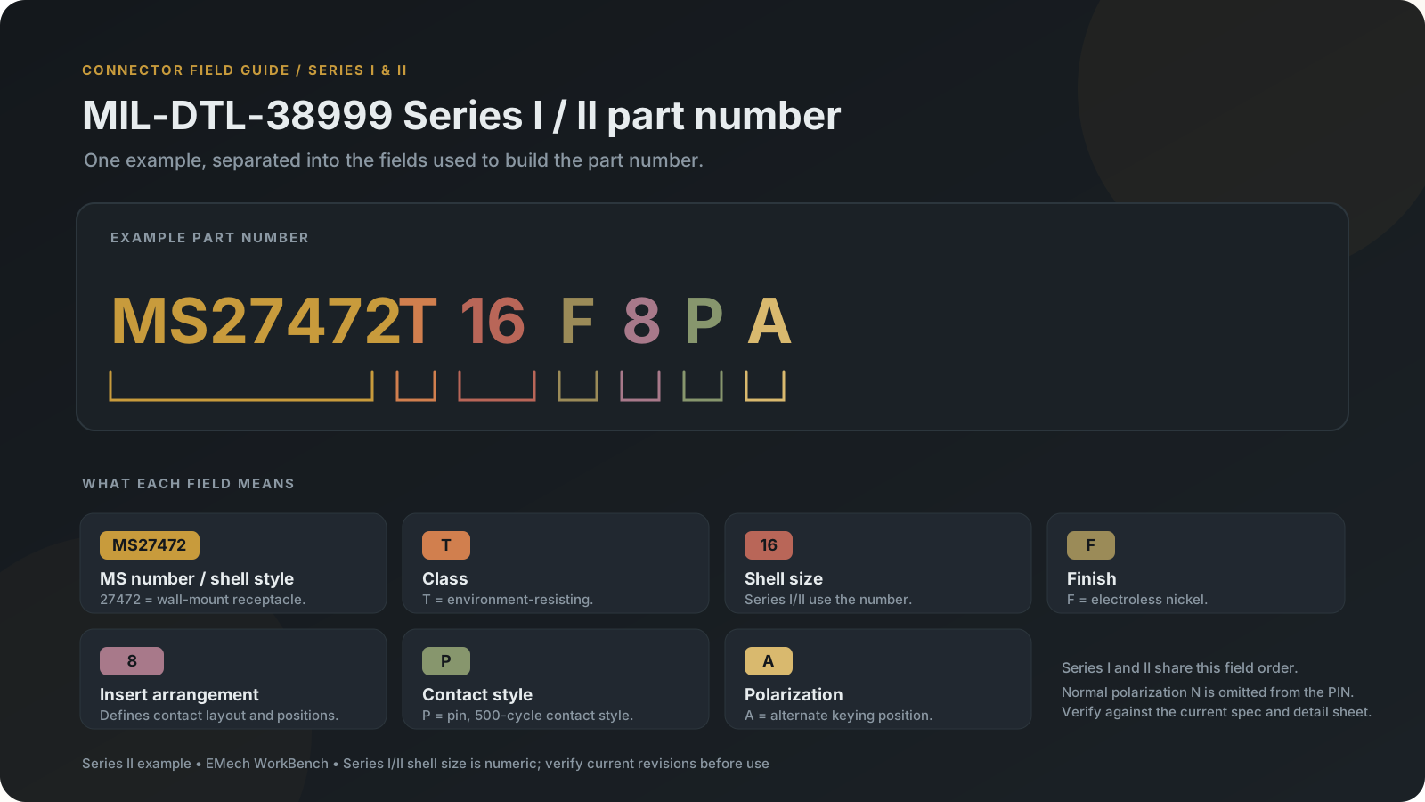
Read each field
| Field | Example | What it identifies |
|---|---|---|
| MS shell-style number | MS27472 | The connector detail sheet and shell style. The available MS numbers differ between Series I and Series II. |
| Class | T | The connector class. In the current data, T is environment-resisting, G is its space-grade variant, Y is hermetic, and H is the space-grade hermetic variant. |
| Shell size | 16 | The shell-size number itself. Series I and II do not use the letter shell-size code used by Series III and IV. |
| Finish | F | Shell finish/coating code. The available finish choices depend on the connector family. |
| Insert arrangement | 8 | The contact layout. Available arrangements depend on series and shell size and are based on MIL-STD-1560 data. |
| Contact style | P | Contact gender and style; for this example, pin, 500-cycle crimp contacts. |
| Polarization | A | The keying position. Normal polarization N is omitted from Series I/II part numbers; non-normal positions appear as a letter. |
Shell-style numbers represented in the current builders
Series I
| MS number | Style in the current dataset |
|---|---|
MS27466 | Wall-mount receptacle, crimp type |
MS27468 | Jam-nut receptacle, crimp type |
MS27467 | Straight plug, crimp type |
MS27469 | Wall-mount receptacle, solder type, hermetic seal |
MS27470 | Jam-nut receptacle, solder type, hermetic seal |
MS27471 | Solder-mount receptacle, solder type, hermetic seal |
The current Series I builder contains 6 of the 15 shell styles identified in its source supplement. A style missing from this table may be outside the tool's scope; absence does not establish that the specification prohibits it.
Series II
| MS number | Style in the current dataset |
|---|---|
MS27472 | Wall-mount receptacle, crimp type |
MS27474 | Jam-nut receptacle, crimp type |
MS27473 | Straight plug, crimp type |
MS27475 | Wall-mount receptacle, solder type, hermetic seal |
MS27476 | Box-mount receptacle, solder type, hermetic seal |
MS27477 | Jam-nut receptacle, solder type, hermetic seal |
MS27478 | Solder-mount receptacle, solder type, hermetic seal |
The current Series II builder contains 7 of the shell styles in its source supplement. Use the builder's coverage notice for the exact implemented scope.
Class and finish choices in the current tool data
The builder uses class and finish as separate fields for Series I and II. The currently represented classes are T and G for general-purpose connectors, and Y and H for hermetic connectors. Finish choices are:
| Finish code | Current dataset description |
|---|---|
A | Aluminum, cadmium yellow, conductive with nickel underplate |
B | Aluminum, cadmium olive drab, conductive |
C | Aluminum, anodic, nonconductive |
D | Aluminum, fused tin, conductive |
E | Stainless steel, passivated, conductive |
F | Aluminum, electroless nickel, conductive |
L | Stainless steel, electrodeposited nickel, conductive |
R | Aluminum, electroless nickel, conductive; higher corrosion requirement than F |
T | Aluminum, nickel-fluorocarbon polymer, conductive |
U | Aluminum, cadmium yellow, conductive; higher corrosion requirement than A |
AA | Aluminum, tri-nickel alloy, conductive |
AB | Aluminum, tin-zinc, conductive |
N | Stainless steel, electrodeposited nickel, conductive; hermetic family |
These are the finish choices encoded in the current data. Selection rules depend on class and shell family; use the builder's available choices rather than assuming every finish applies to every connector.
Shell-size ranges
- Series I: shell sizes 9, 11, 13, 15, 17, 19, 21, 23, and 25.
- Series II: shell sizes 8, 10, 12, 14, 16, 18, 20, 22, and 24.
The number appears directly in the part number. For example, 16 in MS27472T16F8PA is shell size 16.
Contact-style options
General-purpose choices represented in the current Series I/II data:
| Code | Meaning |
|---|---|
P | Pin, 500-cycle |
S | Socket, 500-cycle |
H | Pin, 1,500-cycle contact |
J | Socket, 1,500-cycle contact |
R | Pin, rhodium-plated contact |
M | Socket, rhodium-plated contact |
G | Pin, heavy-gold-plated contact |
U | Socket, heavy-gold-plated contact |
Hermetic contact styles represented by the tool are pin types: P solder cup, X eyelet termination, and C feed-through. Hermetic contacts are fixed in the insert. The same letter can therefore describe a different termination in the hermetic family than in the general-purpose family; follow the selected shell style and the tool's field descriptions.
Polarization positions
The current Series I and II data includes normal N and alternate positions A, B, C, and D. For Series I at shell size 9, and Series II at shell size 8, positions B and C are not offered in the source table. Normal N is represented by no trailing polarization letter in the PIN; other selected positions appear explicitly.
Verify before use
The builder reflects a bounded dataset based on MIL-DTL-38999N with Amendment 2, its supplement where noted, and MIL-STD-1560 arrangement data. Series I and II implement only subsets of their shell-style sheets. Confirm the exact part number, shell style, class, finish, contacts, and mating interface against the current specification and detail sheet before design release or purchase. This site does not currently provide live supplier price or lead-time data.